|
LonWorks Ethernet Adapter
Features
-
Connect LonWorks networks to
TCP/IP Ethernet networks for commercial, industrial,
residential and utility applications
-
LAN<=>LON 100% transparent
data-flow transfer
-
Ethernet:
-
10MBaseT Ethernet interface
-
Static or acquired IP address
-
Capable of process at least
160 packets per seconds
-
LonWorks
-
Twisted pair (TP/FT-10,
TP/XF-1250 and TP/XF-78) LonWorks channel support
-
Virtual SLTA-10 or SLTA
LonWorks network interface
-
LNS (NSI) or LonManager API
(MIP) support
-
Up to 255 adapters could be connect to one PC
-
Network drivers for Windows
and Linux available
-
Local or remote configuration,
monitor and control support
-
Optional password protection
-
DIN-rail mounting
Overview
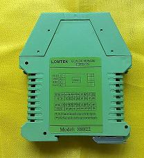
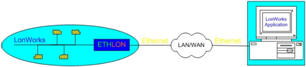
ETHLON, LonWorks Ethernet
Adapter, is a high-performance LonWorks interface for use with
laptop, desktop or embedded computers equipped with a TCP/IP
interface and a compatible operating system, relays the data
between its Ethernet port and the LonWorks port, though TCP/IP
and LonWorks work in a completely different ways. Designed for
use in LonWorks control network that require local or remote
host to monitor, manage, or diagnose the network, ETHLON is the
ideal way to gain central remote access to several control
systems while still using the same software your LonWorks system
was designed for. By extending LonWorks access over Internet
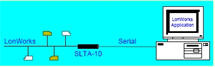
Protocol (IP), ETHLON acts as a directly replacement for a
LonTalk Serial Adapter such as an SLTA-10 or SLTA, establishing
remote access without any major software changes.
 |
 |
| (a) Conventional
Approach |
(b) ETHLON Solution |
ETHLON is a VSLA (Virtual
Serial LonTalk Adapter) device, redirects Ethernet as a virtual
serial port, and recognized as a Serial LonTalk Adapter by
LonWorks system. VSLA device uses the VSDP (Virtual Serial Port
Driver) to create a number of virtual serial ports on the PC -
one per ETHLON you want to address. Each port works exactly like
a normal hardware port but in reality reroutes the data via the
TCP/IP network. With the VSDP installed you can continue to use
your existing LonWorks applications as if one Echelon's SLTA-10
(or SLTA) was attached to your PC's serial port. So you could use
standard drivers of SLTA or SLTA-10 and SLTALink from Echelon
which are accepted by all LonWorks users with universal virtual
serial port driver which are widely accepted by IT world, while
all existing LonWorks software do not need any modify. Up to 255 devices could be
connected to ONE PC running LNS/LonManager Server.
ETHLON utilizes a UDP/IP
protocol for LAN communications. The UDP/IP is a simple protocol
that is supported by any standard TCP/IP networking including
the Internet. There are also several settings that can cause a
UDP packet to be sent depending on the amount of data already
found in the LonWorks buffer or the delay in the arrival of
LonWorks data. Note: It is important to understand the
difference between the data packet and UDP packet. The data
packet is a logical chunk of data that makes sense to the
LonWorks network. UDP packet is a block of data transferred
using the UDP protocol. One data packet maybe transferred over
the LAN in several UDP packets.
ETHLON separates LonWorks
protocol processing between the host processor and this virtual
serial adapter. The virtual serial adapter and NSI handle layers
1 through 5 of the LonTalk protocol. This significantly reduces
overhead in the host processor since it does not have to deal
with lower layer network services such as media access control,
collision avoidance, acknowledgments, retries, duplicate message
detection, message validation, authentication, and priority
processing.
The host processor is left to
run the application program and handle the layer 6 and 7
protocol services, i.e., network variable processing and
explicit message processing. The host can easily send and
receive network variable updates and explicit messages through
these services.
Separating the upper two layers
of the LonWorks protocol from the lower five layers has the
added benefit of making ETHLON independent of its host
application. The host application and its network variables can
be changed at any time without modifying the adapter. This
lowers development and maintenance costs since ETHLON does not
have to be tailored to an application.
ETHLON can have to up to 4096
network variables, each potentially connecting to more than
32,000 network variables on other devices. This limit is higher
than the Neuron Chip hosted node limit of 62 bound network
variables because the host instead of the Neuron Chip inside the
ETHLON manages the network variable configuration. The use of
bound network variables reduces network loading and increases
system capacity by allowing values to be updated over the
network only when necessary without the need for constant
polling.
The ETHLON Adapter could be a
LNS Network Services Interface (NSI) or Microprocessor Interface
Program (MIP) compatible network interface. This adapter is a
device that enables any host processor with an Ethernet LAN
interface to implement LNS or LonWorks applications and to
communicate with other devices using the LonWorks protocol. A
cuttable jumper selects between the NSI mode (default) and MIP
modes of operation.
The LNS network operating
system allows any number of installation, maintenance,
monitoring, and control devices to exist in a system and to
adapt to network configuration changes automatically. Users can
reconfigure the system from any user interface device anywhere
on the network and ensures that all monitoring and control
stations are always up-to-date with respect to the system's
configuration. When used with the appropriate software, the LNS
Network Services Interface functionality of the ETHLON adapter
allows the attached host to run LNS applications, such as the
LonMaker Integration Tool, as well as other LNS tools.
In both NSI mode and MIP mode,
a ETHLON adapter also allows any host to implement the upper
layers of the LonWorks protocol, so applications on the host can
send and receive network variable updates and explicit messages,
as well as poll network variables. This capability extends the
reach of LonWorks technology to a variety of hosts including
desktop and embedded microprocessors.
Typical applications for ETHLON
include monitoring and control devices based on computers
running Windows or Linux. The module
incorporates an LNS NSI that permits the module to be used as
the network interface for LNS applications.
Network drivers are available
for Windows and Linux. The simple driver is
implemented on the host processor to manage the interface with
the virtual serial adapter. This allows the same host
application to be used with multiple network interfaces, up to 255 adapters could be
connect to one PC, preserving any investment in host application
development.
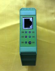
Status LEDs display current
mode of operation and errors.
Specification
|
Ethernet |
|
Protocol |
TCP,
UDP, ARP, ICMP(ping) |
|
Media |
Two
Twisted Pair V |
|
Buffer
Size |
Two
independent 255 bytes for LAN and virtual serial port |
|
Interface |
10MbaseT, RJ45 |
|
Mode |
Normal,
Programming, Firmware download |
|
LonWorks |
|
Transceiver Type |
FTT-10A,
TPT/XF-78, TPT/XF-1250 |
|
Topology |
Bus or
Free, Single-ended or Double-ended |
|
Data
Communication Type |
Transformer-isolated Twisted Pair |
|
Network
Wiring |
22 to
16AWG Twisted Pair |
|
Control |
Service
Pin |
|
Electric |
|
Supply
Voltage |
24VDC
(18-32VDC) |
|
Power
Consumption |
<2W |
|
Environmental |
|
Operating Temperature |
0 to +70
DegC |
|
Non-operating Temperature |
-40 to
+85 DegC |
|
Operating Humidity |
10-90%
RH @ 50 DegC, non-condensing |
|
Non-operating Humidity |
95% RH @
50 DegC, non-condensing |
|
Physical |
|
Dimensions |
L100mm x
W22.5mm x H112mm |
|
Weight |
approx.
200g |
|
Protection |
IP20 |
|
Installation |
DIN-rail
Mounting |
|
Others |
|
Indicators |
Power
Supply |
Red |
|
Ethernet |
Red &
Green |
|
Status |
Red &
Green |
|
LonWorks
Communication |
Yellow |
|
Service |
Green |
|
Certification |
CE, FCC,
RoHS |
Configuration
DS
Manager
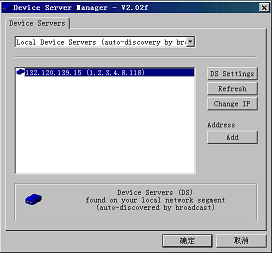
DS Manager would scan the whole network using
broadcast mode automatically after start up, and find all
ETHLON modules in the LAN.
Generally ETHLON IP-address could be specified according
with that of LAN using Change IP.
|
Using the WINIPCFG to find out your
PC's IP address
1 Choose RUN from the Start menu of
the windows, the RUN dialog will open
2 Type winipcfg into the OPEN textbox
and press OK, the WINIPCFG dialog will open
3 Note the IP-address displayed and
click OK, the dialog will close
4 Choose an IP-address that is close
to the set for your PC
|
Click DS Settings, then the ETHLON Device Server Manager
configuration dialog will open:
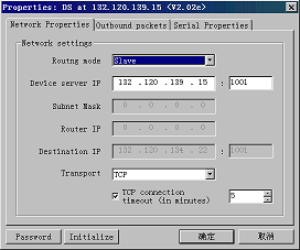
Network properties:
Slave mode is default routing mode. Device server IP and
port are auto-configured. Please specify the port number
larger than 1000. TCP or UDP network transport protocol
could be specified. If Master mode is selected, please
specify the Subnet Mask, Router IP-address (optional),
Destination IP-address and its port number (This number
should be the same as Device Server).
Outbound packets: The default configuration
needs no modification.
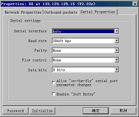
Serial Properties: Serial interface - Auto,
Baud rate - 38400bps, Parity - None, Flow control - None, Data
bits - 8 bits. Important Note: "On-the-fly" and "Soft
Entry" should not be enabled. These options are preserved for
future uses.
Password:
supply password protection avoiding modify configuration
parameters wrong.
Initialize:
recover configuration with factory settings
|
TIP: Please
choose "SKIP" just ignore the warnings if poped up
during configurations. It is caused by upgraded
firmware version mismatches what was previously
registered in DS Manager. |
VSP
Manager
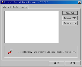
Running VSP Manager opens Properties window.
The window contains a list of existing VSPs. By default the
list is empty. You can Add VSPs, Remove VSPs, and edit
Properties of existing VSPs.
Adding new VSP
Click Add VSP button - New virtual serial
port dialog will appear. Note: Depending on the windows
version you are using and the speed of you PC this may take
up to 20 seconds. "New Hardware Found" message may be displayed by
windows system at this time. Please wait patiently for the
dialog to open.
The dialog has the following controls:
Port setting: drop-down selects a number for
a COM port being created. The drop-down only shows remaining
available ports. Choose any port (i.e. COM10). Note: The
actual serial ports (i.e. COM1) are also included, and a
warning dialog would appear if they were selected. Please
check the "Enable RX/TX data logging" if you want to monitor
the data flow of this port, but "Send On-The-Fly serial
setting changes to Device Server" should be Disabled.
IP setting: These options must be set.
Transport protocol: TCP (default).
Specific local port: No port number is
specified in Slave mode. When ETHLON is in Master mode, a
port number same as DS Manager specified should be used. If
you have several ETHLONs attached to one PC using several
VSP, you need specify a different local port number for each
VSP.
Destination IP: Specify destination ETHLON IP
address and port number. Click Destination DS... select
destination ETHLON, program would automatically set
corresponding IP address and port number.
VSP Outbound packets
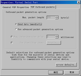
The default settings need no modification ("Send data immediately" Enabled).
Editing and deleting existing VSP
To edit existing VSP select it in the list of
available ports and press Properties button (or double-click
on the desired port in the list). To delete VSP press Remove
VSP button.
Port
Monitor
Run Port Monitor, enable "Monitor RX&TX Data" and select the
virtual port (ETHLON) you want to monitor. If there are data
transferring, you would see HEX codes in the log window.
Note: If data flow could not be monitored, please check
whether "RX/TX data logging" is enabled in VSP Manager.
SLTA driver
The driver is not shipped with ETHLON, the latest version
could be obtained from the Echelon web site.
The SLTA network driver is installed by adding a DEVICE
command to the DOS CONFIG.SYS file. Edit the CONFIG.SYS file
to include the line:
DEVICE=C:\LONWORKS\BIN\LDVSLTA.SYS [options]
Substitute your drive and directory name if other than
C:\LONWORKS\BIN. Reboot the PC after adding this line to
load the driver. For example, the following command would be
used with a ETHLON installed on VSP COM12 as device LON5:
DEVICE=C:\LONWORKS\BIN\LDVSLTA.SYS /P12 /D5 /B38400 /A
Note: 1. /Un option used to set interrupt request number
should not be specified.
2.
Up to 9 ETHLONs could be connected to ONE PC using MIP mode,
as D1-D9.
3.
Please refer Echelon LTS-20 User Guide for other more
information on SLTA driver.
SLTA-10 driver & SLTALink Manager
The Windows95/98 or NT software is not shipped with ETHLON,
available on the Echelon web site,
LonWorks
SLTA-10 Serial LonTalk Adapter Software for Windows
98/2000/XP,
LTS-20 &
SLTA-10 NSI Mode Software for Windows 95/98 and Windows
NT/2000 Drivers.
Note: Please refer Echelon LTS-20 User Guide for more
information on SLTA-10 driver.
Run SLTALink Manager, select [Link]->[New..], a dialog
appear:
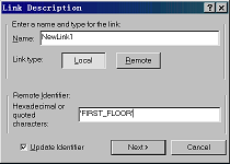
Define a new link name, i.e. NewLink1. Select Link type as
"Local" Name ETHLON you want to link a Remote identifer,
i.e. "FIRST_FLOOR" with "Update Identifier" enabled, then click
"Next>" button.
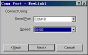
Specify the Virtual Comm Port parameters as you used to do
with SLTA-10 and SLTALink. Select the VSP as "Serial Port"
and the speed same as you selected in VSP Manager (default
is "38400". Click "Next>" button, then "Finish" with default
options left.
Note: If the installed VSP has not appeared in Comm Port
Dialog, please modify the registery using REGEDIT
mannually: Add the name and key value (i.e. name: COM10, key
value: COM10) in "HKEY_LOCAL_MACHINE\Hardware\DeviceMap\SerialComm"
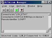
Click [Link]->[Connect Now], ETHLON would be connected
successfully with GREEN status LED on, you can use a virtual
SLTA-10 now.
Note: Please refer Echelon LTS-20 User Guide for more
information on SLTALink.
Connectors & Indicators
Summary of Status LED signals
(Excludes LEDs) signaling in the Firmware Download mode)
-
Ethernet
LEDs
|
Green LED
Blinks |
IP packet is
received |
|
Red LED is ON |
LAN collision
error |
|
Service Switch |
Push-button,
be used to broadcast the 48bit Neuron ID on the
LonWorks network during installation |
|
Service LED |
Blinking |
Unconfigured |
| |
OFF |
Configured |
| |
ON Steadily |
Applicationless, a critical error has been detected
by the firmware |
Network Driver
Order Information
| Order Code |
Description |
Unit Price (Euro) |
| 88122-FT10 |
Ethernet 10MBaseT - LonWorks TP/FT-10
Adaptor |
Contact Us |
| 88122-TP78 |
Ethernet 10MBaseT - LonWorks TP/XF-78
Adaptor |
Contact Us |
| 88122-TP1250 |
Ethernet 10MBaseT - LonWorks
TP/XF-1250 Adaptor |
Contact Us |
|